目录
- 关键概念
- 视口
- 相机
- 光源
- 材质
- 3D对象
- 命中测试(鼠标交互)
- 3D对象中2D控件渲染
- 外部导入3D模型
WPF的3D功能可以在不编写任何c#代码的情况下进行绘制,只需要使用xaml即可完成3D图形的渲染。本文主要讲述了WPF-3D中的关键概念, 以及常用到的命中测试、2d控件如何在3D对象中进行渲染,除此之外,还演示了如何导入外部3D模型。
关键概念
视口
视口指的是图像要展示在哪里,可以理解为展示图形的舞台。在WPF中视口使用Viewport3D标签表示。
相机
如果把视口比作舞台,那相机就可以理解为观众的眼睛,不同的眼睛位置会看到不同的角度。
<Viewport3D>
    <!--相机-->
    <Viewport3D.Camera>
        <!--透视相机-->
        <PerspectiveCamera Position="8,5,10"
                           LookDirection="-7,-2,-10"
                           FarPlaneDistance="40"
                           NearPlaneDistance="10"
                           FieldOfView="60">
            <PerspectiveCamera.Transform>
                <RotateTransform3D CenterX="1.5" CenterY="1" CenterZ="0.5">
                    <RotateTransform3D.Rotation>
                        <AxisAngleRotation3D Angle="45" Axis="0,1,0"/>
                    </RotateTransform3D.Rotation>
                </RotateTransform3D>
            </PerspectiveCamera.Transform>
        </PerspectiveCamera>
        <!--正交相机,用法类似-->
        <!--<OrthographicCamera/>-->
</Viewport3D.Camera>
光源
没有光源也就看不到3D对象
<!--光线-->
<ModelVisual3D>
    <ModelVisual3D.Content>
        <Model3DGroup>
            <!--散射光线-->
            <AmbientLight Color="#FFF"/>
            <!--平行光-->
            <!--<DirectionalLight Color="#FFF" Direction="0,-1,0"/>-->
            <!--点光源-->
            <!--<PointLight Position="0,0,0"/>-->
            <!--锥形辐射光:手电筒-->
            <!--<SpotLight Position="0,0,0" Direction="0,0,-3"/>-->
        </Model3DGroup>
    </ModelVisual3D.Content>
</ModelVisual3D>
材质
3D几何对象只是将轮廓定义出来,表面是没有定义的,所以需要使用材质来展现出不同的物体表面。也可以理解为3D几何对象只是勾勒出物体的轮廓,而材质则是上颜色。
<ModelUIElement3D >
    <ModelUIElement3D.Model>
        <GeometryModel3D>
            <!--材质-->
            <GeometryModel3D.Material>
                <!--散射材质-->
                <DiffuseMaterial Brush="Blue"/>
                <!--镜面材质-->
                <!--<SpecularMaterial SpecularPower="1" Brush="Blue"/>-->
                <!--自发光材质-->
                <!--<EmissiveMaterial Color="Green" />-->
            </GeometryModel3D.Material>
            <GeometryModel3D.Geometry>
                <MeshGeometry3D Positions="0,0,1 0,2,1 3,2,1 3,0,1
                                           0,0,0 0,2,0 3,2,0 3,0,0"
                                TriangleIndices="2,3,7 7,6,2 1,5,4 0,1,4"/>
            </GeometryModel3D.Geometry>
        </GeometryModel3D>
    </ModelUIElement3D.Model>
</ModelUIElement3D>
3D对象
3D对象则是具体的对象,在WPF中视口使用<ModelUIElement3D>标签表示。在WPF中,图形是以三角面片作为最基本的展示单元,因为三角形是最稳定的即三个点可以确定出唯一的一个平面,任何复杂的图形都是由多个三角面片组成的。在给TriangleIndices属性赋值时,一定注意三个点的顺序。
命中测试(鼠标交互)
想要使用鼠标点击得到某个图形,可以在具体的某个3D对象中,增加MouseLeftButtonDown事件
<ModelUIElement3D MouseLeftButtonDown="ModelUIElement3D_MouseLeftButtonDown">事件中可以进行改变颜色等操作
private void ModelUIElement3D_MouseLeftButtonDown(object sender, MouseButtonEventArgs e)
{
    ModelUIElement3D mui3d = sender as ModelUIElement3D;
    var model = mui3d.Model as GeometryModel3D;
    (model.Material as DiffuseMaterial).Brush = Brushes.Orange;
}
如果有很多3D对象,在每个具体的对象上面增加事件会很麻烦,也可以直接在Viewport3D中增加事件
<Viewport3D MouseLeftButtonDown="Viewport3D_MouseLeftButtonDown">在时间中急性转换处理
private void Viewport3D_MouseLeftButtonDown(object sender, MouseButtonEventArgs e)
{
    Viewport3D viewport3D=sender as Viewport3D;
    Point location=e.GetPosition(viewport3D);
    HitTestResult hitTestResult=VisualTreeHelper.HitTest(viewport3D, location);
    if (hitTestResult != null)
    {
        ...//具体操作
    }
}
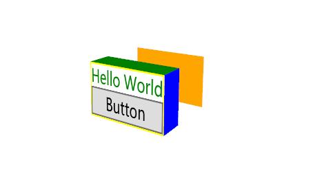
3D对象中2D控件渲染
如果要在3D对象中增加控件,可以使用Viewport2DVisual3D标签,实现如下图所示的效果。
<Viewport3D>
 <Viewport2DVisual3D>
    <Viewport2DVisual3D.Geometry>
        <MeshGeometry3D Positions="0,0,1 0,2,1 3,2,1 3,0,1
                       0,0,0 0,2,0 3,2,0 3,0,0"
            TriangleIndices="0,2,1 0,3,2 6,4,5 6,7,4"
            TextureCoordinates="0,1 0,0 1,0 1,1"/>
        <!--TextureCoordinates:表示的二维平面坐标,原点:左上角-->
    </Viewport2DVisual3D.Geometry>

    <Viewport2DVisual3D.Material>
        <DiffuseMaterial Viewport2DVisual3D.IsVisualHostMaterial="True" Brush="White"/>
    </Viewport2DVisual3D.Material>
    <Viewport2DVisual3D.Visual>
    <Border BorderThickness="1" BorderBrush="Yellow">
        <StackPanel>
            <TextBlock Text="Hello World" Foreground="Green" />
            <Button Content="Button" Click="Button_Click"/>
        </StackPanel>
    </Border>
    </Viewport2DVisual3D.Visual>
 </Viewport2DVisual3D>
<Viewport3D>
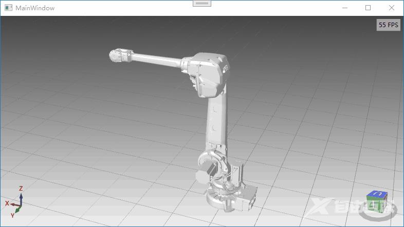
外部导入3D模型
在wpf中绘制3D模型还是非常麻烦的,在实际工作中用的比较多的是从外部导入已有的3d模型。推荐一个比较好的第三方库HelixToolKit
<Window x:Class="WpfApp2.MainWindow"
        xmlns="http://schemas.microsoft.com/winfx/2006/xaml/presentation"
        xmlns:x="http://schemas.microsoft.com/winfx/2006/xaml"
        xmlns:d="http://schemas.microsoft.com/expression/blend/2008"
        xmlns:mc="http://schemas.openxmlformats.org/markup-compatibility/2006"
        xmlns:local="clr-namespace:WpfApp2"
        xmlns:helix="http://helix-toolkit.org/wpf"
        mc:Ignorable="d"
        Title="MainWindow" Height="450" Width="800">
    <Grid>
        <helix:HelixViewport3D  Name="viewPort3d"
                                ShowViewCube="True"
            ViewCubeBackText="后" ViewCubeFrontText="前" ViewCubeHeight="100" ViewCubeWidth="100"
            ViewCubeVerticalPosition="Bottom"
            ViewCubeHorizontalPosition="Right"

            ShowCoordinateSystem="True"
            CoordinateSystemLabelForeground="Red"
            CoordinateSystemHorizontalPosition="Left"
            CoordinateSystemVerticalPosition="Bottom"

            ShowFrameRate="True"

            IsViewCubeEdgeClicksEnabled="False">


            <helix:HelixViewport3D.Camera>
                <PerspectiveCamera FieldOfView="45"
                                   LookDirection="0,0,-414.387754871885"
                                   FarPlaneDistance="30000"
                                   NearPlaneDistance="0.1"
                                   Position="9.9475983006414E-14,91.037123633789,414.387754871885"
                                   UpDirection="0,1,0"/>
            </helix:HelixViewport3D.Camera>

            <helix:HelixViewport3D.Background>
                <LinearGradientBrush EndPoint="0.5,1" StartPoint="0.5,0">
                    <GradientStop Color="#444" Offset="0"/>
                    <GradientStop Color="#EEE" Offset="1"/>
                </LinearGradientBrush>
            </helix:HelixViewport3D.Background>
            <helix:GridLinesVisual3D Width="16000" Length="16000" Thickness="2" MinorDistance="500" MajorDistance="500" Fill="Gray" />

            <!--很重要,没有灯光场景是黑的-->
            <helix:DefaultLights/>

            <ModelVisual3D x:Name="model"></ModelVisual3D>

        </helix:HelixViewport3D>
    </Grid>
</Window>
namespace WpfApp2
{
    public partial class MainWindow : Window
    {
        List<string> modelPaths = new List<string>();
        string basePath = AppDomain.CurrentDomain.BaseDirectory + "\\ModelFiles\\";
        public MainWindow()
        {
            InitializeComponent();
            modelPaths.Add("IRB4600_20kg-250_LINK1_CAD_rev04.stl");
            modelPaths.Add("IRB4600_20kg-250_LINK2_CAD_rev04.stl");
            modelPaths.Add("IRB4600_20kg-250_LINK3_CAD_rev005.stl");
            modelPaths.Add("IRB4600_20kg-250_LINK4_CAD_rev04.stl");
            modelPaths.Add("IRB4600_20kg-250_LINK5_CAD_rev04.stl");
            modelPaths.Add("IRB4600_20kg-250_LINK6_CAD_rev04.stl");
            modelPaths.Add("IRB4600_20kg-250_LINK3_CAD_rev04.stl");
            modelPaths.Add("IRB4600_20kg-250_CABLES_LINK1_rev03.stl");
            modelPaths.Add("IRB4600_20kg-250_CABLES_LINK2_rev03.stl");
            modelPaths.Add("IRB4600_20kg-250_CABLES_LINK3_rev03.stl");
            modelPaths.Add("IRB4600_20kg-250_BASE_CAD_rev04.stl");

            this.Loaded += MainWindow_Loaded;

            viewPort3d.RotateGesture = new MouseGesture(MouseAction.RightClick);
            viewPort3d.PanGesture = new MouseGesture(MouseAction.LeftClick);
        }
        private void MainWindow_Loaded(object sender, RoutedEventArgs e)
        {
            viewPort3d.Camera.LookDirection = new Vector3D(2038, -5200, -2930);
            viewPort3d.Camera.UpDirection = new Vector3D(-0.145, 0.372, 0.917);
            viewPort3d.Camera.Position = new Point3D(-1571, 4801, 3774);

            this.model.Content = InitializeModels(this.modelPaths);
        }

        private Model3DGroup InitializeModels(List<string> modelsNames)
        {
            Model3DGroup group = new Model3DGroup();
            try
            {
                ModelImporter import = new ModelImporter();

                foreach (string modelName in modelsNames)
                {
                    var materialGroup = new MaterialGroup();
                    Color mainColor = Colors.White;
                    //EmissiveMaterial emissMat = new EmissiveMaterial(new SolidColorBrush(mainColor));
                    DiffuseMaterial diffMat = new DiffuseMaterial(new SolidColorBrush(mainColor));
                    //SpecularMaterial specMat = new SpecularMaterial(new SolidColorBrush(mainColor), 2000);
                    //materialGroup.Children.Add(emissMat);
                    materialGroup.Children.Add(diffMat);
                    //materialGroup.Children.Add(specMat);

                    var link = import.Load(basePath + modelName);
                    GeometryModel3D model = link.Children[0] as GeometryModel3D;
                    model.Material = materialGroup;
                    model.BackMaterial = materialGroup;

                    group.Children.Add(link);
                }
            }
            catch (Exception e)
            {
                MessageBox.Show("未知异常:" + e.StackTrace);
            }
            return group;
        }
    }
}
HelixToolKit使用文档
以上就是WPF实现绘制3D图形的示例代码的详细内容,更多关于WPF 3D图形的资料请关注自由互联其它相关文章!